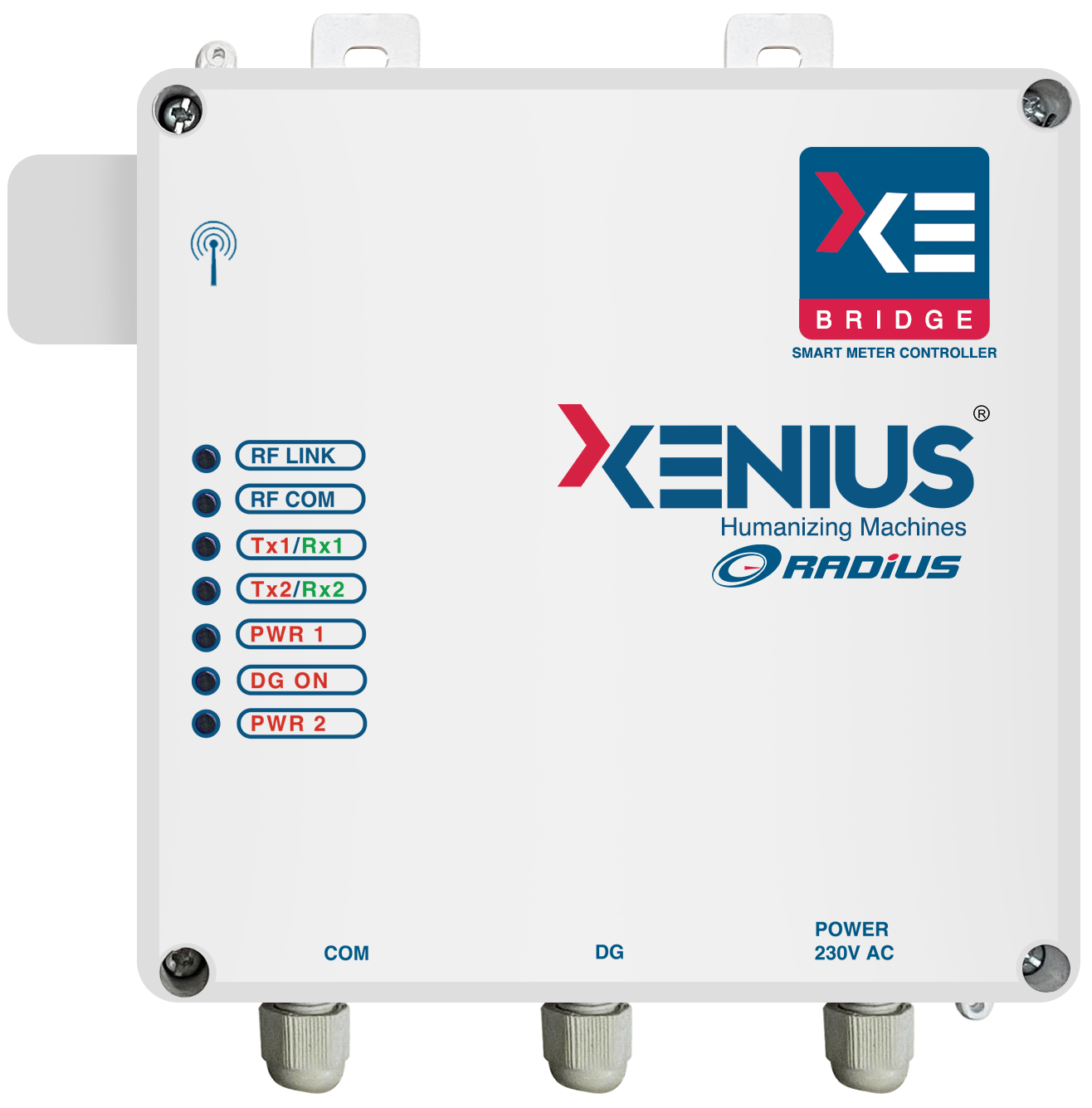
Smart Coordination Bridge
Smart M2M Coordination Bridge is a robust, reliable and configurable communication device that helps orchestrate and coordinate the communication amongst a group of field devices through a local area network. It also enables the communication of all such field devices with the backend Xenia IoT Platform through Xenius M2M Gateway for their real-time monitoring and control. With advanced capabilities like edge intelligence, field upgrades and a host of protocol support, it helps connect heterogeneous field devices for multiple IoT application areas.
As an example use case, in case of Smart Metering, Xenius Coordination Bridge can communicate and control up to twelve smart electronic meters by forming a local area network through multiple communication options like RS232, RS485, wired probes or wireless RF network. On the other side, it can be interfaced with the Xenius M2M Gateway using a wired or wireless connectivity for connectivity to the backend Xenia IoT Platform. Through its Digital and Analog input/output ports, Xenius Coordination Bridge is capable of interfacing, sensing and controlling additional sensors and relays of energy meters or additional devices like Diesel Generators, Smart Street Lights and Smart Water Management Systems.

Would you like to know more about us ?
Technical Specifications
- Coordination Bridge (DCU) for Energy Meter
- Coordination Bridge (DCU) for DGs
| Specification | Details |
| Communication in different configuration | 865 MHz wireless for Neighborhood Area Network (NAN) side and RS485 based wired network on meter side for communication with smart meter and another smart sensor which makes non-smart meter to smart. NAN is a network comprising of group of Bridge devices. Each bridge device in tern collect data from meters attached on RS485 bus |
| Baud Rate | Capable to communicate with the meters as per meter’s standard communication baud rates |
| Firmware Upgrade | Firmware Over The Air (FOTA), all the controller are FOTA enabled and there should be no requirement to physically change or upgrade the firmware |
| Parameter Upgrade | Over The Air. All the threshold parameters (i.e load management) are configurable from backend over the air |
| Source sensing | Able to receive source info. And output to downside meters for correct source info (DG/GRID) Keep accounting of source at different level like associated meters with respect to current source |
| RTC | Yes |
| GPS | NO |
| Number of meters | Supports aggregation of up to 12 meters |
| Tamper | Issues immediate alert on opening of casing |
| Casing | A compact housing of polycarbonate/engineering plastic/Metallic enclosure having IP55 degree of protection |
| Power Consumption | <= 5 Watts |
| Operating Voltage | 90V AC to 280V AC P-N, 50 Hz with a variance of upto 5% |
| Rated impulse withstand voltage /Surge | 10 kV |
| Power Backup | No power backup |
| Operating Conditions | -20o to 70o C, Humidity: - 95% RH (Non - Condensing) |
| Operational Indicator | LED for NAN communication (RF) Power and meter side communication |
| Specification | Details |
| Communication in different configuration | Downside DI (wired connection with DG), Upside -RF (Connection with Coordination Bridge (DCU) |
| Operating Voltage | 90V AC to 280V AC P-N, 50 Hz with a variance of upto 5% |
| NAN Interface Port | RF |
| Rated impulse withstand voltage/Surge | 6.5 kV |
| Power Backup | No |
| Network Security | 128 Bit AES |
| Mounting Arrangement | Panel and wall mounting option |
| Enclosure Material | Material is of unbreakable fire retardant and high- quality polycarbonate as approved by the purchaser. Resistant to action of chemical alkalis and other solvents. IP 55 |
| Antenna | External antenna with a flexible antenna with proper mounting arrangements |
| Firmware Upgrade | Firmware Over The Air (FOTA), all the controller are FOTA enabled and there should be no requirement to physically change or upgrade the firmware |
| Digital Inputs | 2 DI ports |


